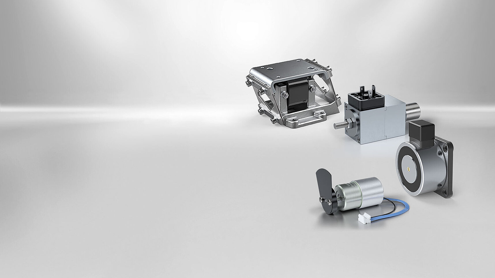
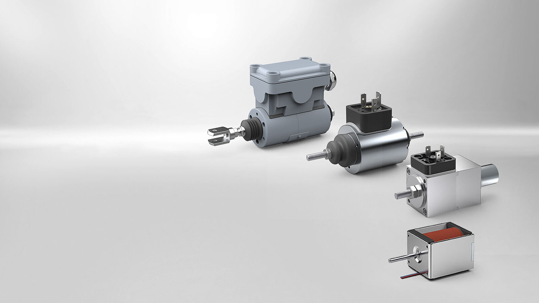
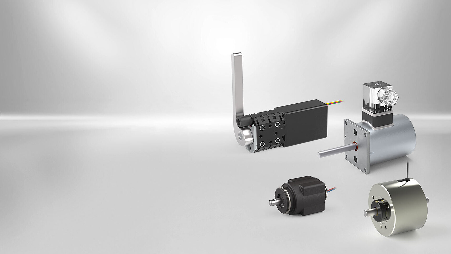
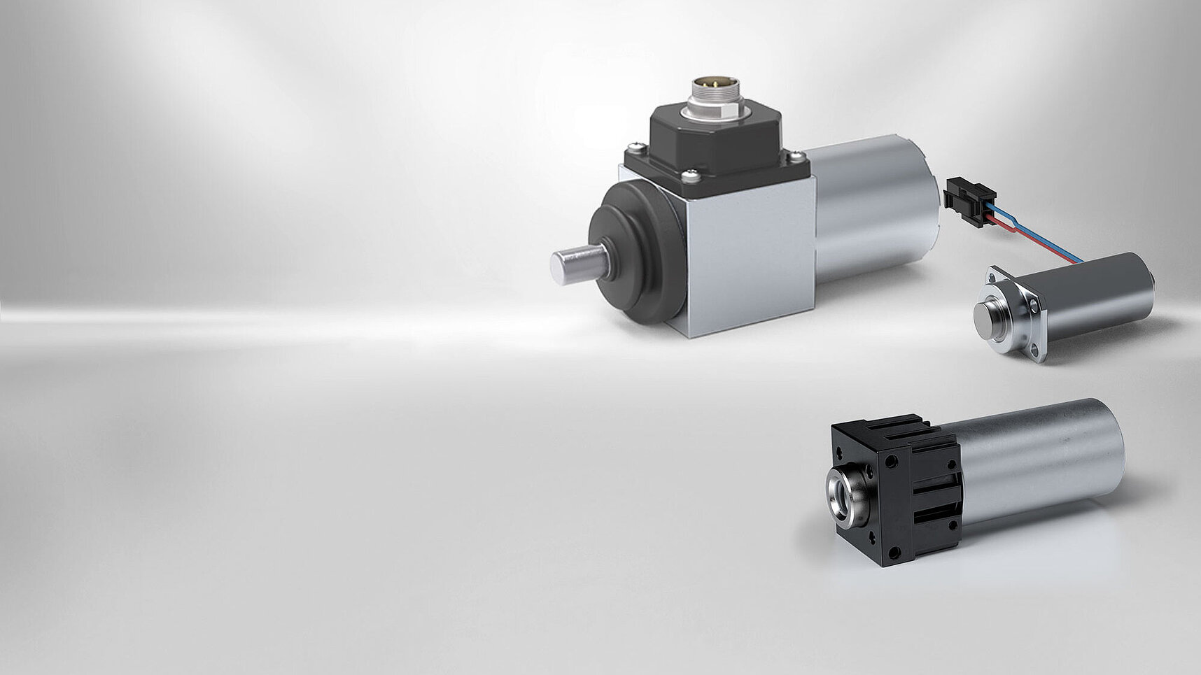
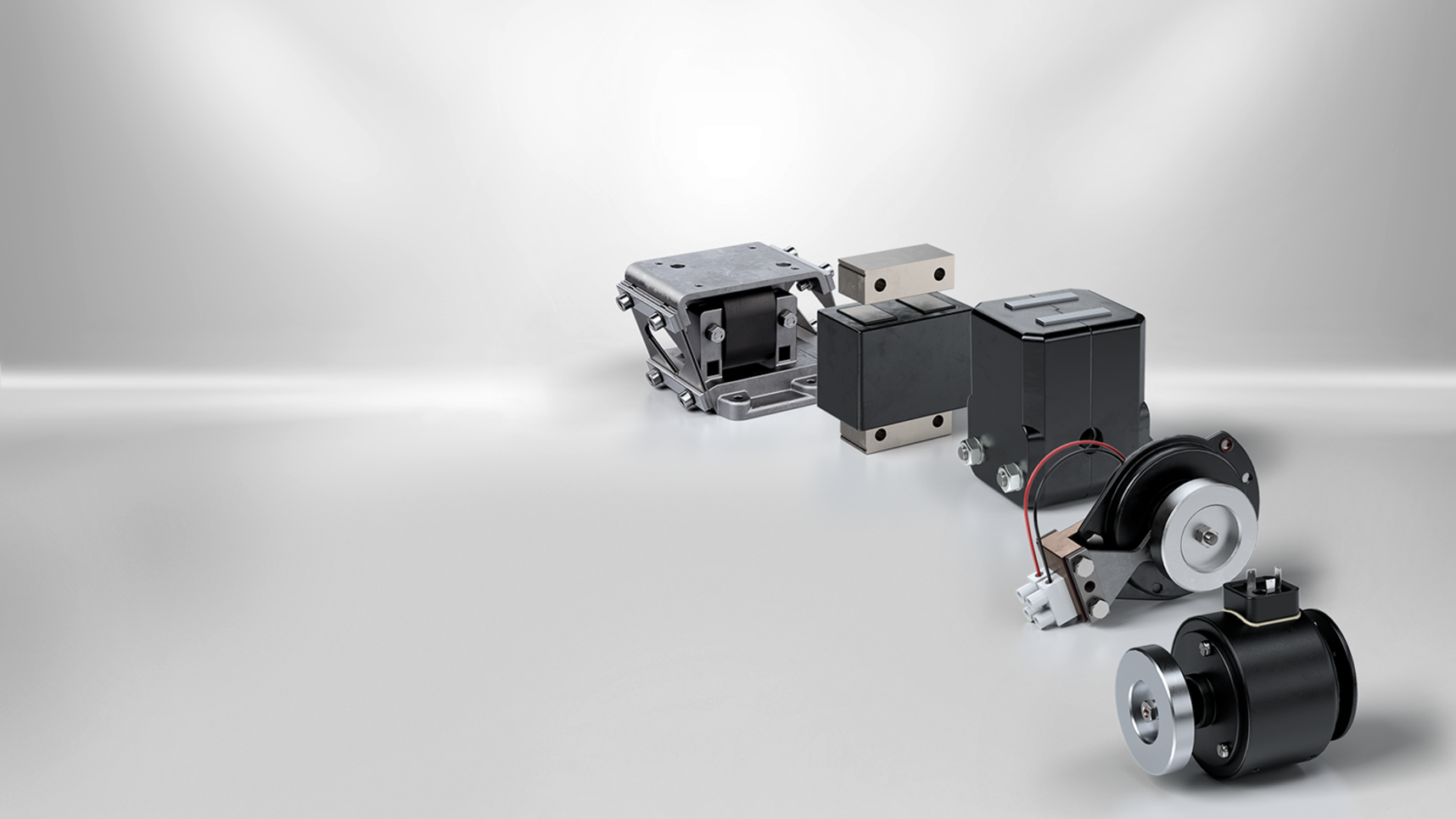
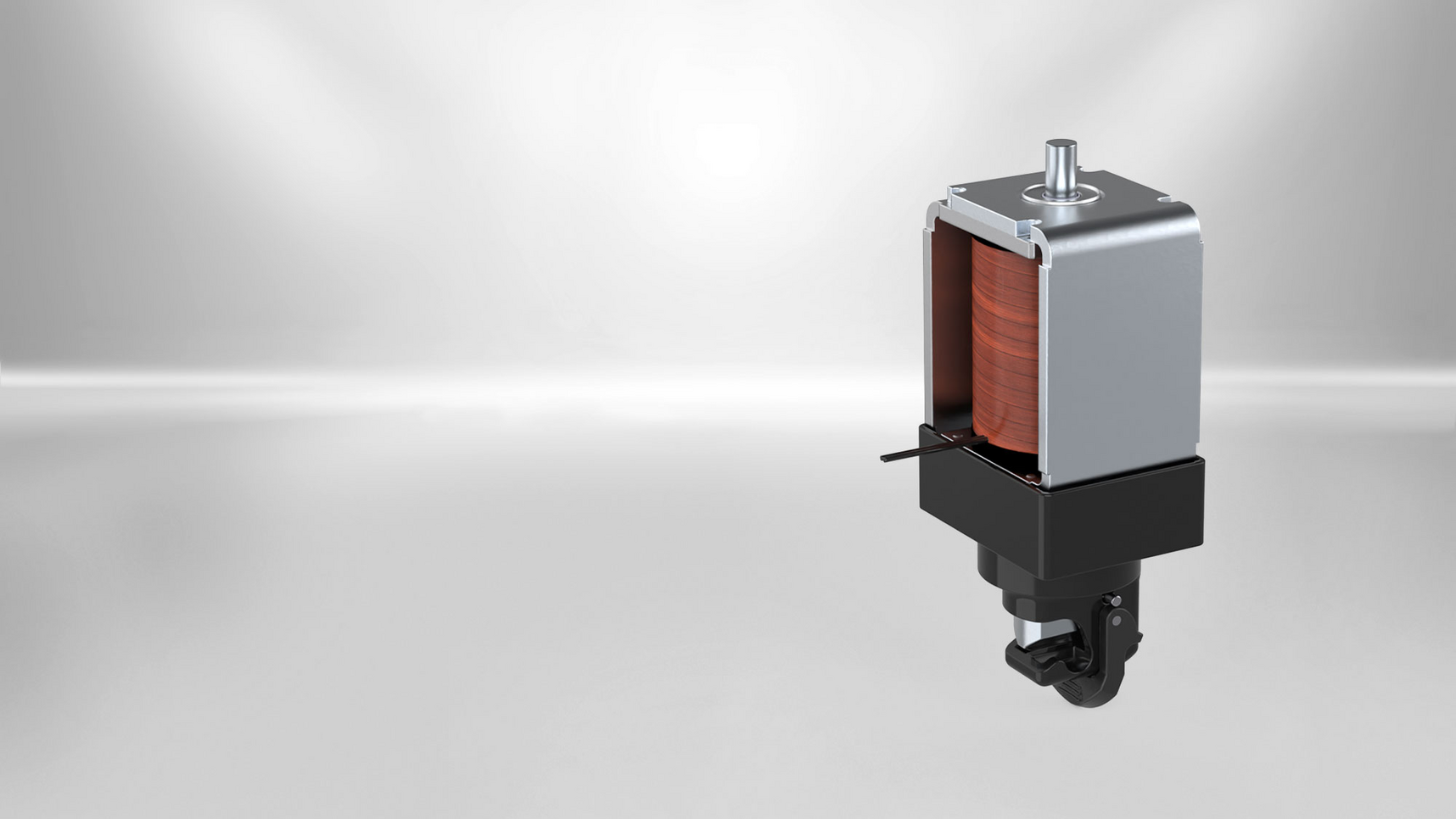
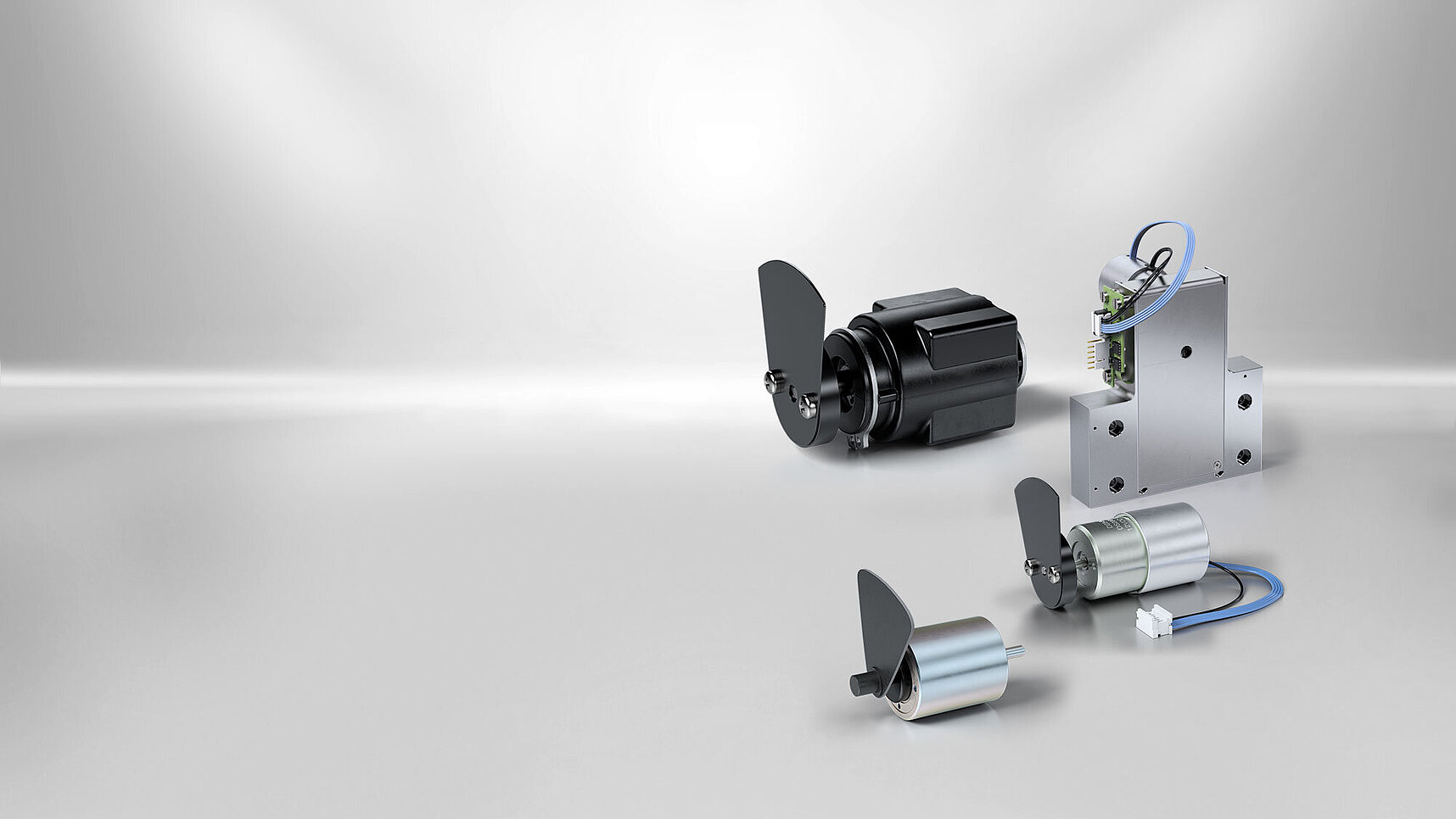
With over 100 years of experience in the development and manufacture of electromagnetic components, KENDRION is a specialist in innovative solutions for numerous industries such as mechanical engineering, automation, energy and medical technology.
What components comprise an electromagnet?
Solenoid body
Part that contains the excitation winding and conducts the magnetic flow (also: solenoid housing)
Excitation winding
Winding to create the magnetic field (also: magnetic coil, coil, winding)
Excitation system
Module consisting of magnet body and excitation winding
Voltage winding
Excitation winding that receives current, which depends on the supply voltage and the excitation resistance
Current winding
Excitation winding that determines the current of upstream equipment, i.e. which mainly depends on the excitation winding resistance (e.g. current regulation).
Armature
Magnetically conducting parts moved or held by the magnetic field.
What components comprise an electromagnet?
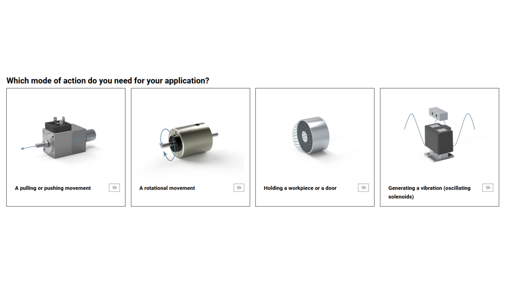
Actuating solenoid
Component for affecting a limited lengthwise or rotating movement
Linear solenoid
Actuating solenoid that triggers a stroke movement via the effect of a magnetic field created by the excitation winding (also: single stroke solenoid)
Rotating solenoid
Actuating solenoid that triggers a rotating movement via the effect of a magnetic field created by the excitation winding. With regard to their functionality, rotating solenoids may be designed as single stroke or reverse stroke rotating solenoids featuring single or double currentless limit positions (monostable-bistable)
Oscillating solenoid
Actuating solenoid that triggers a periodic back and forth movement via the effect of a magnetic field created by the excitation winding in a spring-mass system featuring an oscillating frequency, which is generally related to a fixed proportion of the frequency to the applied voltage
Holding magnets, holding solenoid
Device or component for adhering ferromagnetic objects
Reversing linear solenoid
An actuating solenoid with electromagnetic force effect in two movement directions. Depending on the excitation, the stroke movement takes place from the respective stroke start position to the associated stroke limit position. In this case, the stroke limit position of one direction is simultaneously the stroke start position of the opposite movement direction
Single stroke spreader solenoid
A linear solenoid that is mainly used for ventilating block brakes due to its design and technical data
Single stroke double spreader solenoid
A linear solenoid consisting of two single stroke spreader solenoids that is mainly used for ventilating block brakes due to its design and technical data
Pulsing linear solenoid
A device featuring an armature stroke movement caused by electromagnetic forces from the stroke start position to the stroke limit position, whereby the armature is held by an integrated permanent solenoid while the current is switched off
Control solenoid, proportional solenoid, regulating solenoid
Linear stroke solenoids that are mainly used to activate valves in hydraulic controls and regulating devices due to their design and technical data
Valve solenoid
A linear solenoid that is mainly used for activating valves in pneumatic and hydraulic control devices due to its design and technical data
Single stroke solenoid with pivoting armature
A linear solenoid featuring an armature that completes a pivoting movement around a pivot point
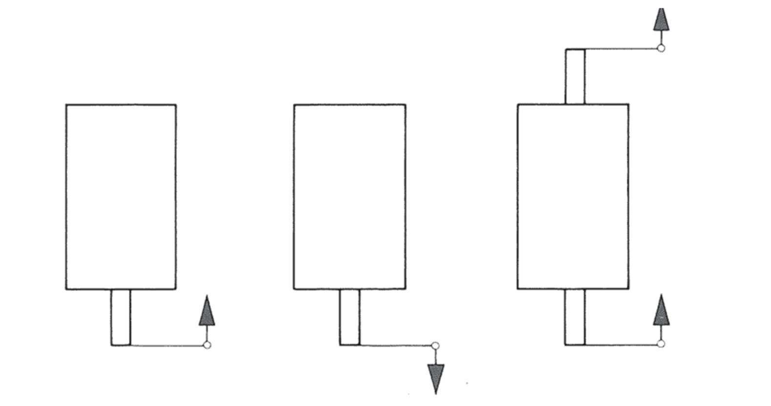
Pulling and pushing design
Kendrion actuating solenoids may be divided into three variations with regard to the created movement: pulling, pushing, and pushing and pulling. This refers to both linear stroke solenoids and rotating solenoids.
What quantities define the characteristic curve of the electromagnet?
Magnetic force F
The useful part of the force produced in the stroke direction inside the actuating magnet, i.e. the force reduced by friction.
Stroke force Fstroke
The magnetic force that acts outwards in consideration of the associated component of the armature weight. The stroke force is equal to the magnetic force in case of horizontal installation
Holding force FH
In case of direct current actuating solenoids, this is the magnetic force in the stroke limit position. In case of alternating current solenoids, the average value of the magnetic force periodically fluctuating with the alternating current in the stroke limit position.
Residual holding force
The holding force remaining after deactivation
Residual actuating force
The force required to return the armature to the stroke start position after deactivation. (in case of rotating solenoids, the force corresponds with the torque)
Solenoid stroke s
The path covered by the armature from the stroke start position and stroke limit position.
Stroke start position s1
The position of the armature before starting the stroke movement or after completing the return movement.
Stroke limit position s2
The designed position of the armature in the solenoid after completing the stroke movement

How does a stroke-force characteristic curve of an electromagnet look?
The graphic display of the magnetic force depending on the solenoid stroke. There are three different characteristic curves in the direction of the stroke limit position.

How is stroke work calculated?
Stroke work W
The integral of the magnetic force F above solenoid stroke s. The stroke work comprises a potential stroke work component W1 and a kinetic stroke work component W2.
What time definitions are relevant for operation of electromagnets?
Activation delay t11
The time from activation of the excitation current until starting the armature movement
Stroke time t12
The time from the start of the armature movement from the stroke start position until reaching the stroke limit position.
Attraction time t1
The time from activation of the excitation current until reaching the stroke limit position. The sum of the activation delay t11 and stroke time t12.
Release delay t21
The time from deactivation of the excitation current until starting the return movement of the armature.
Return time t22
The time from the start of the return movement from the armature until reaching the stroke start position.
Release time t2
The time from deactivation of the excitation current until reaching the stroke start position. The sum of the release delay t21 and return time t22.
What electrical terms are relevant for the operation of electromagnets?
Activation current
In case of alternating current devices, this is the current that activates during excitation when the armature is held in the stroke start position and the compensation process is finished.
Nominal voltage UN
The value of the electrical voltage that is indicated by the manufacturer for a device or a component and refers to the operating and performance aspects.
Preferred nominal voltage
The nominal voltage that devices are usually available with ex warehouse
Nominal current IN
In case of electrical devices, the supply current assigned by the manufacturer to the device or the component to designate or identify it. Generally, the current consumption of voltage windings under nominal conditions, as well.
In case of alternating voltage windings, the current that activates as the holding current under nominal current, when the armature in the stroke limit position
Holding current IH
In case of alternating voltage devices or components, this is the current that activates upon excitation of the nominal voltage, when the armature is in the stroke limit position and the compensation process has completed.
Activation current IE
In case of alternating current devices and components, this is the current that activates during excitation with nominal voltage when the armature is held in the stroke start position and the compensation process is finished.
Nominal power PN
Suitable rounded power value to designate and identify the device or the component. Also generally the power consumption under nominal conditions (20⁰ coil temperature).
Holding power
The product of the nominal voltage and holding power in case of alternating voltage device or components
Insulating material class
The assignment of winding insulating materials to thermal classes with regard to their limit temperature according to DIN EN 60085.
Protection class
Classification of devices with regard to protection measures against electrical shock according to DIN EN 61140.
IP protection class
Scope of protection of the electromagnetic device against direct contact or penetration of solid objects or water. Specification as an IP code according to DIN EN 60529.
Why must the maximum activation duration of an electromagnet be observed?
Duration
The time that passes between activation and deactivation of the excitation current.
Currentless pause
The time that passes between deactivation and reactivation of the excitation current.
Cycle time
The sum of activation duration and the currentless pause
Cycle sequence
A one-time or periodically recurring sequencing of cycle time values of different sizes.
Continuous operation
Operation during which the activation duration is so long that the steady-state temperature is reached.
Short-term operation S2
Operation during which the activation duration is so short that the steady-state temperature is not reached and the currentless
pause is so long that the device cools down to the ambient temperature (tolerance 2K).
Intermittent operation S3
Operation during which the activation duration and the currentless pause alternate regularly, whereby the pauses are so short that the device does not cool down to the ambient temperature.
Switching operations z
Number of working cycles
Switching frequency Z
The number of switching operations per hour.
Operating temperature condition
The over-temperature determined according to VDE 0580 increased by the ambient temperature. If nothing else is indicated the ambient temperature amounts to 35°C.
Deviating reference temperature
Our solenoids can also be used under deviating reference temperatures if the permitted activation duration is multiplied by the corresponding calculation factor. The stroke work completed by the winding at operating temperature is not influenced by this. The diagram is used to determine the relevant activation duration in case of deviating reference temperatures.
How is the relative activation duration calculated?
The catalogue specifications for the relative activation durationof Kendrion solenoids refer to a cycle time of 5 minutes, if nototherwise indicated. The maximum activation duration results from this for the various relative activation duration:
40% Activation duration max. 120 s
25% Activation duration max. 75 s
15% Activation duration max. 45 s
5% Activation duration max. 15 s
These maximum values may not be exceeded. In case of doubt, application take places for the respective longer relative activation duration.
How is the effective electromagnetic force produced?
Magnetic remanence
When a ferromagnetic component is magnetised, a portion of the magnetisation remains in the material after deactivation of the excitation. This condition is referred to as remanenceor residual magnetism. Put simply, it may be expected that the majority of magnetising materials behave as if they were weak permanent magnets. The remanence determines the residual holding power. After pulling off the workpiece from the holding surface once, the remanence nevertheless disappears continuously. The greater the air gap δL, the lower the expected remanence and the residual holding force will be.
Permeabilität µ
This indicates the permeability of a material in case of magnetic fields. The relative permeability µrel µrel is the amplification factor related to the permeability µ0 of the vacuum.
µ0=1,256*10(-6) (Vs/Am)
µ0=µrelµ0
In case of ferromagnetic materials: µrel >> 1
Magnetic flow Φ
In equivalence of the electrical circuit Φ is defined as the flow size of the magnetic field according to current I in the electrical circuit. The better the magnetic properties (permeability µ), the greater the magnetic flow Φ at otherwise equal parameters will be. Information is indicated in Weber (Wb) or Vs.
1Wb=1Vs
Magnetic flow density B
If the magnetic flow is related to the conducting cross-sectional area in the magnetic circuit, the magnetic flow density B that results is indicated in T (Tesla).
1T=1 (Vs/m2)=1 (Wb/m2)


